woensdag 1 oktober 2014

Decoding Itho RF Protocol

My objective was to control my Itho CVE Eco Fan RF-enabled mechanical ventillation. I bought an RTL-SDR device to decode the protocol. I found that my RF switch sends a signal on 868.260Mhz. I'm not quite sure what the protocol is: * It looks like it creates chirps which slightly increase or decrease in frequency * Some chirps are longer I've made a sample with a samplerate of 3.200.000 Hz. * With each press of a button 3 chirps will be transmitted. * Each chirp constists of +/- 49688 samples. * Between two chirps is a pause of 1577538 samples. * The chirp uses a sine wave with a length of approx 16,5 samples * Most of the time every 400 samples there is a rude phase shift, 
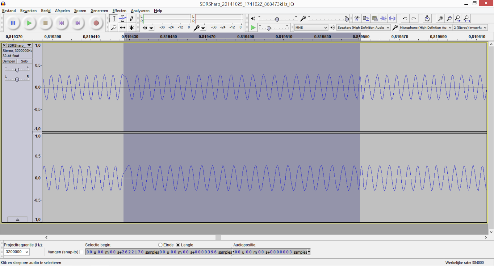
With Audacity I scrolled through one chirp from start to end and saw a difference in sine frequency. The change in frequency made it look like some parts of the signal "moved" left and others to the "right". This alternated and switched with every phase shift. I've took notes: L= meant moving left, R= meant moving right. I got the following pattern: RLRLRLRLRLRLRLRLRLRLRLRLRLRLRLRRLRLRLRLRLRLRLRLRLRLRLRLRLLRLRRLLRLRRLRLLRRLRLLRLRRLRLRLRLLRRLRLRLRLRLRLRLRLRLLRLRLRRLLRLRRLRLRL 1234567890123456789012345678901234567890123456789012345678901234567890123456789012345678901234567890123456789012345678901234567890 1 2 3 4 5 6 7 8 9 0 1 2 3 In the pattern i noticed that sometimes the phase shift didn't occur. The "moving left/right" of the sines is because the frequency moved up/down. In "Wavelet Explorer" i made a spectral analysis and got the following picture: This picture is the best indication of how the protocol works. Notes: At a samplerate of 3.200.000Hz every 400 samples a phase-shift occurs. If every part betwee phase-shifts (400 samples) is a bit. This would mean that the data rate would be: 3200000/400=8000bps

When Googling some more on the used K110 IC, i found: "K110 B3 is an Infineon TDK5110 ASK/FSK Transmitter 868/433 MHz" (http://www.domoticaforum.eu/viewtopic.php?f=7&t=127&start=45)
---
It's working.
I've used a HopeRF Miniwireless 868 RF69W module, soldered between pin D7 (Arduino) and DIO2 (RF69) a wire. With this wire it's possible to use "Continuous Mode". In this mode the signal is directly controlled by the Arduino.


  if (!rf69.init()) Serial.println("init failed");

  if (!rf69.setFrequency(868.260)) Serial.println("setFrequency failed");

  RH_RF69::ModemConfig t = { 0x60,  0x06, 0x83, 0x00, 0x9D, 0xf4, 0xf4, 0x00};
  rf69.setModemRegisters( &t );
  pinMode(7, OUTPUT);

void loop() {
        // WC beneden
      int signalConnect1[] =    {15,41,43,45,57,59,63,73,75,95,99,101,103}; // might not be correct
      int signalDisconnect1[] = {15,41,43,45,57,59,63,73,75,91,93,95,97,107,109};  // might not be correct
      int signalLow1[] =        {15,41,43,45,57,59,63,73,75,95,99,101,103};
      int signalMedium1[] =     {15,41,43,45,57,59,63,73,75,93,97,101,105,107,109};
      int signalHigh1[] =       {15,41,43,45,57,59,63,73,75,91,93,95,97,107,109};
      int signalTimer1[] =      {15,41,43,45,57,59,63,71,73,79,81,89,91,93,95,105,109};
      int signalLength1 = 113;

      // Wc boven
      int signalConnect3[] =    {15,49,53,59,61,63,65,73,75,95,99,101,103,107,109}; // might not be correct
      int signalDisconnect3[] = {15,49,53,59,61,63,65,79,95,101,107,109};
      int signalLow3[]=         {15,49,53,59,61,63,65,73,75,95,99,101,103,107,109};
      int signalMedium3[]=      {15,49,53,59,61,63,65,73,75,93,97,101,105};
      int signalHigh3[] =       {15,49,53,59,61,63,65,73,75,91,93,95,97};
      int signalTimer3[] =      {15,49,53,59,61,63,65,71,73,79,81,89,91,93,95,105,107};
      int signalLength3 = 113;    


      // Badkamer
      int signalConnect2[] =    {};
      int signalDisconnect2[] = {};
      int signalLow2[]=         {31,57,61,63,67,71,73,77,81,89,91,111,117,119,123};
      int signalMedium2[]=      {31,57,61,63,67,71,73,77,81,89,91,109,113,115,117,121,125};
      int signalHigh2[] =       {31,57,61,63,67,71,73,77,81,89,91,107,109,111,113,125};
      int signalTimer2[] =      {31,57,61,63,67,71,73,77,81,87,89,95,97,105,107,109,111,115,121,123,125};
      int signalLength2=129;
     
     
      int signalConnectRepeats =4 ;
      int signalDisconnectRepeats =4 ;
      int signalTimerRepeats =3;

      int* signal = signalLow1;
      int signalRepeats = signalTimerRepeats;
      int signalLength = signalLength1;

    for (int idx2=0;idx2<3 idx2="" p="">    {
      rf69.setOpMode(RH_RF69_OPMODE_MODE_TX);
   
      int flip = LOW;
      int bc = 0;
      for (int idx=0;idx        if  (signal[bc]==idx)      
        {
          bc ++;
        } else
        {
          flip = !flip;
        }
        digitalWrite(7,flip);
        delayMicroseconds(110);
      }  
      rf69.setOpMode(RH_RF69_OPMODE_MODE_STDBY);
      delay(500);
    }
   
    delay(20000);

Looking at the data i've gathered. I suspect the bitstream is manchester encoded. It will try to switch from "Continous Mode" to "Packet Mode" as this would save energy when listening for a signal.
-- to be continued --

Reviving an old Barbie doll'd up Nail Printer

I bought on eBay the Barbie doll'd up nail printer for my girlfriend and daughter. These nail printers are long out-of-production and also the ink cartridges are scarce. Also the software is hard to install on modern operating systems. Problem 1: Installing the Nail printer software I downloaded the Windows 7 software package "Nail_Printer_Update_v1.0.0.24.exe" from http://service.mattel.com/us/technicalproductdetail.aspx?prodno=V5152&siteid=27&catid=506. When i tried to install it onto my Windows 7 x86 laptop it gave an "error -1603" when installing the printer driver. The main application installed fine. I traced the problem to a multi-lingual issue in the package. The package supports multiple language, but misses the files for languages other than english. My solution was to duplicate some folder for language of my operating system (dutch). 1. Execute "Nail_Printer_Update_v1.0.0.24.exe" which you downloaded from service.mattel.com 2. Navigate with Windows Explorer to your temp folder during installation, for me: C:\Users\Laptop\AppData\Local\Temp\ 3. During installing two temporary folders will appear. In one of the folder there are two installation files: "Barbie Doll'd Up Nails Printer Driver (x86).exe" and "Barbie Doll'd Up Nails Printer Driver (x64).exe" 4. Copy the "Barbie Doll'd Up Nails Printer Driver (???).exe" to a temporary location, for instance the "desktop" 5. Execute the "Barbie Doll'd Up Nails Printer Driver (???).exe" from the desktop 6. Again watch the temp-folder for a file: "Barbie Doll'd Up Nails Printer Driver.msi" and copy it to your "desktop" 7. Execute from command-line: msiexec /a "Barbie Doll'd Up Nails Printer Driver.msi" /qb /targetdir=c:\barbie This will extract the contents of the MSI to disk 8. Navigate with Windows Explorer to "C:\barbie\program files\Mattel\Barbie Doll'd Up Nails Printer Driver\MLDOprc\i386" 9a. Make a copy of the folder "English" and rename the copy to your language. Possible languages: english, arabic, chi_simp, chi_trad,czech,danish,dutch, finnish,french,german,greek,hebrew, hungaran,italian,japanese,korean,norwegan, polish,portibrn,portbrzl,russian,spanish,swedish,turkish 9b. Another option is to modify the file "MLDOprc.inf". Look for "%LANG_PATH%" and replace all occrences with "English". Problem 2: My ink cartridges were dry as a desert I made holes in the ink cartridge and injected hot water with a syringe. Because of the hot water the ink became liquid again. The water also ruined the ink. I had to make a hole for Yellow. The holes for Magenta and Cyan were already marked on the cartridge with an identation. The two identation closest to the printhead-connectors were for the color Magenta (Redish). The identation in the right-bottom corner is for Cyan (blueish). Next to the Cyan identation i had to make a hole without a marker, but there is the Yellow ink compartment. I looked at the pictures here to drill holes: http://www.printerfillingstation.com/Refill-Instructions/Lexmark/L8.htm Problem 3: How to get good ink in it. I drained the ink cartridges with the syringe and took ink from some Pixma MX870 ink cartridges. Although this did work somewhat, the quality was very poor. Some good tips: * Cover the other holes during refilling otherwise the ink might flow into the chambers of the other colors. I've ordered Lexmark 43 cartridges as these seem quite similar. It will arrive in a few days and i hope it will work. The Lexmark 43 XL cartridges do seem to work. I've not yet tested it thouroughly though. Problem 4: How to get rid of the humongous AC/AC Converter. My printer came with a US adapter, with a AC/AC Converter (230V->115V). If i get the ink cartridge to work correctly it needs to be replaced. AC adapter: DC24V, 500mA, Connector: yet to be determined, inner +, outer -

dinsdag 7 juli 2009

ZigBit's have arrived..


The two ZigBit modules have arrived! They were just as i imagned they would be! Only 4 times smaller. I really suspect some kind of alien technology is used to fabricate these modules. They are Tiny (yes, capital T!).


On the internet i've not been able to find good pictures of the underside of the ZigBit's.


To give an impression of the real-world size: Two cats sniffin' at a ZigBit.

Whoooohww! It's not a toy or something you can eat...
And now i must think of a solution to wire-it-up..


zondag 5 juli 2009

ZigBee enable our cats
One of our cats keeps running of out of our garden. Some time ago she stayed out for days and we found her in some bushes a few hundred meters away. I'm hoping to implant her with a ZigBee chip so i'm able to trace her. ofcourse i wouldn't implant her with a chip !!! I want to make a module for her collar.

Create a ZigBee enabled soil moisture sensor
Hopefully i will then be reminded when to spray my lawn with water on time.
Sensor

Rain-sensor
Audible warning when it starts raining and i've left things out in the garden.

donderdag 2 juli 2009

ZigBit breakout

I prefer not to have to solder wires to the ZigBit's. I'll have to find a solution to solderless connect to the ZigBit's. From the datasheet i found out that the ZigBit pins have a 1mm spacing. This means that i'll be unable to use a standard solderless prototype board.

I thought I had a good idea: create some kind of socket with needles stuck in wood. I thought i then would be able to connect wires to the needles and voila a socket... I printed the mounting-information page of the ZigBit datasheet on true size (25%).... Uhmm... Ok.. That small!!??
I still have to find a way to interface with the zigbits without soldering... The needles will be returned to the sewing box..

Maybe I'll be able to find 18 pin (single/double sided?) edge connectors with 1mm spacing for 0.8mm thickness pcb. Also a 7 pin version.
Something like this?http://nl.farnell.com/samtec/mec1-120-02-s-d-a/connector-card-egde-1mm-40way/dp/1667839

dinsdag 30 juni 2009

Links

µracoli - The µController Radio Communication Library
ICRadio RF230 OEM
Zigbee for Linux
The motherload of answers!
Wiki info

Forum thread

Hardware for programming the ZigBit's

I've read that there are multiple options for programming the ZigBit-module's:
1. via a serial-cable
2. via JTAG

I've found a cable which i'd bought for connecting a phone to my computer. Upon plugging-in it announces itself as an "USB Data Cable". Notice the bump in the USB-connector. It probably contains some type of Usb-Serial-chip. Be looking up the serialnumber: "WT048000317" i found that it probably uses the arkMicroChips "ark3116" chip.


http://www.bobhobby.com/2008/02/25/modify-usb-data-cable-to-use-with-microcontroller-projects/


Also I've found an "USB Link cable" which came with an X10-CM11 module. It announces itself as an "Prolific USB-to-serial Comm Port" device in Windows.


I also have the Sanguino laying around which might act as an in-between. Which reminds me. I also bought an accompanying cable with the Sanguino. Bingo! It annouces itself as an "USB Serial Port".

I will probably start out with programming the ZigBit's via the serial-method.

I just got into contact via Twitter with Aaron Steiner. He uses the Sparkfun RS232 Shifter. Ah ok! Note to self: check which TTL voltage the ZigBig-modules need. I'm unable to verify which the correct TTL voltage is from the datasheet of the ZigBit-modules. Until now i've been unable to find an answer, only the same question. Fortunatly Aaron had the answer which voltage to use: 3.0volt. So propably i'm unable to use one of the three cables i've got lying around, because they have 5.0volt as output.

I've looked around for some JTAG-interfaces which can be used for the ZigBits. Ofcourse Atmel sells their own AVR JTAG ICE MKII interfaces, but for a private person the pricing is too steep and will take the "hobby-factor" away. On Ebay i found two different JTAG ICE MKII clones, which are more nicely priced. For now i've decided to wait for the shipment of the ZigBit's. My options are clear for reprogramming the ZigBit's:
* Buy a USB -> Serial 3.0volt cable
* Buy an MKII clone from Ebay.

JTAG
I found a thread where somebody is trying to program an zigbit with USBProg.